

Request Quote
When you sketch an isolation plan on a utility drawing, it’s natural to mark the repair location first. The plan can look settled until you trace the main beyond that point and find another path feeding pressure toward the work. Adding another stop may seem like a minor revision, but it can reshape the field setup and the operating plan. That’s why deciding whether a single- or double-line stop configuration is better suited for the job at hand requires a closer look, which is what we’re here to do.
At its core, a line stop acts as a temporary valve inserted through a fitting on a pressurized pipe. After a hot tap creates the access opening, the stopping head enters the main and interrupts flow while the surrounding system remains active. The head establishes a boundary at one location; it doesn’t isolate every connection shown beyond that point.
In a single-line stop configuration, one stopping head controls pressure in one direction. The work area therefore needs a dependable limit on the other side, such as a verified closed valve or a confirmed dead end. A double-line stop configuration places one head on each side of the planned work so the two boundaries contain a defined segment.
A single stop often fits work located downstream of one known pressure source. If the main terminates beyond the project or a proven valve bounds the opposite end, one stopping head may complete the isolation. This arrangement can also support work where flow only needs to be blocked or redirected at one point.
Using one stop reduces the number of access fittings and hot taps the project needs. It may also reduce excavation requirements when the site has limited space for equipment. Those advantages can shorten field time, but they only count if the remaining system conditions truly support a one-boundary plan.
The main risk is an incomplete understanding of how water reaches the work area. A looped main can feed from the direction that looked downstream on the original drawing. A cross-connection or a valve that doesn’t hold may create the same problem, so the system must be traced against current records and field conditions before crews rely on one stop.
Double-line stopping is designed for a segment that can receive pressure from both ends. The two heads bracket the work area, which allows crews to drain and depressurize the space between them after verifying the seals. This configuration often supports valve replacement or pipe removal on a main that must remain active outside the work limits.
The second stop does more than extend the equipment schedule. It creates another tapping location and another sealing interface that must be engineered for the actual pipe. It may also require a separate excavation if the work zone is too long for both operations to share a single pit.
Two stops on opposite ends shouldn’t be confused with two barriers against the same pressure source. Each head normally protects one side of the isolated segment. If a project specification calls for double-block-and-bleed isolation, a standard two-ended arrangement may not meet that requirement without added equipment or a purpose-built system.
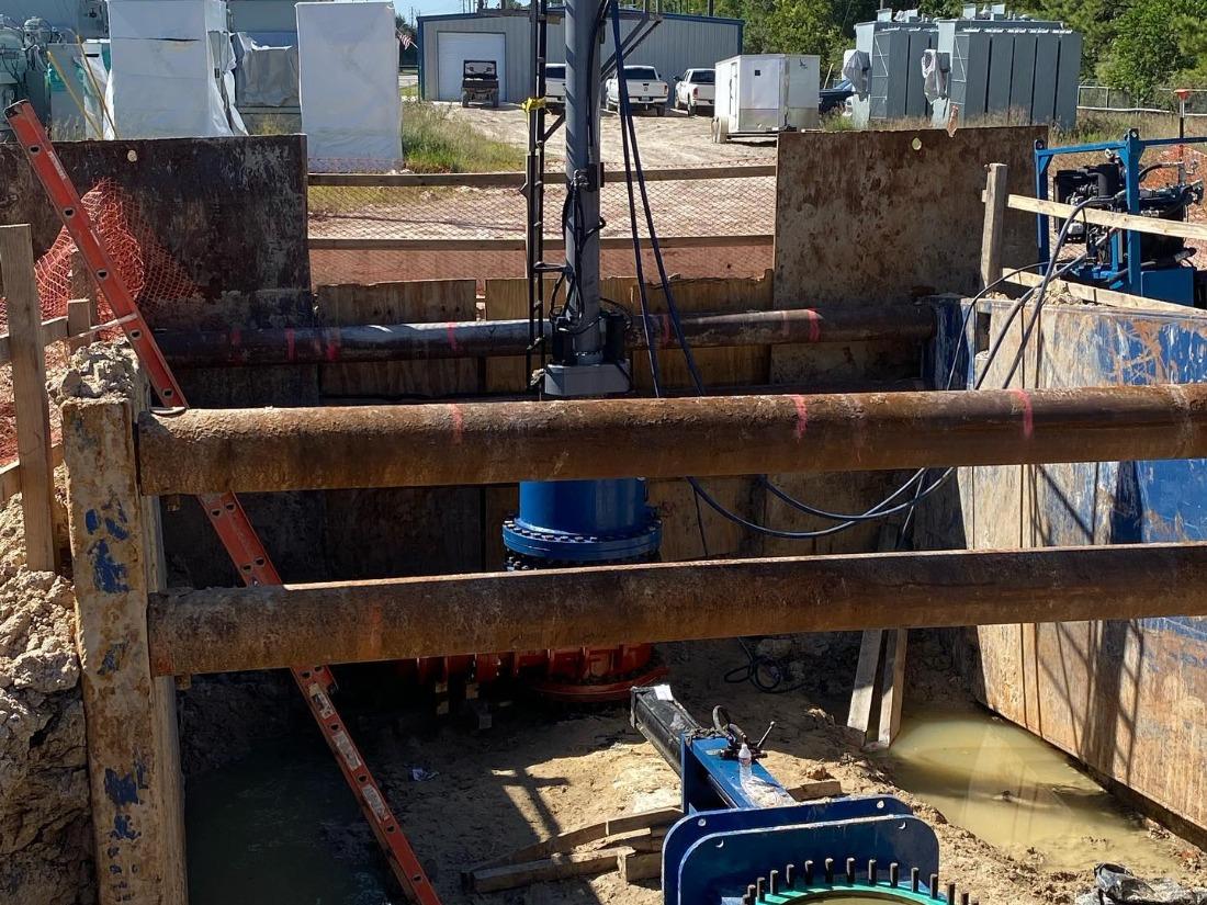
An isolation may protect the work zone while still cutting service to users beyond it. A temporary bypass carries flow from the live side to a connection past the stopped section. With double-line stopping, that route usually spans the full isolated segment; a single stop may also need a bypass when downstream service must continue.
The bypass has to carry the required demand at an acceptable pressure. A smaller temporary line may appear easier to route, yet excessive velocity and head loss can leave the operating system short of what it needs. Fire-flow obligations or process demand may set a higher capacity target than normal consumption alone would suggest.
Routing also affects the stop plan. Temporary piping needs protected space and sound connection points, while every pressure boundary requires testing before service begins. On potable systems, the bypass materials and commissioning procedure must also protect water quality throughout the job.
The proposed stop locations must work on the pipe that crews actually expose. Pipe material and outside diameter guide fitting selection, while internal condition affects how well the stopping head can seat. For a water line stop on an older main, scale or an irregular interior may require cleaning and a closer assessment of sealing before isolation.
Space above the pipe matters because the tapping machine and line-stop actuator need working clearance. A second location can introduce another conflict with traffic or nearby utilities. Moving a stop to resolve that conflict may lengthen the isolated section, altering both drainage volume and bypass routing.
Branches deserve particular attention here. A service connection located between two stops can keep feeding the segment even though both mainline heads are set. Current mapping should be checked in the field so that every possible source in the work zone has a defined control method.
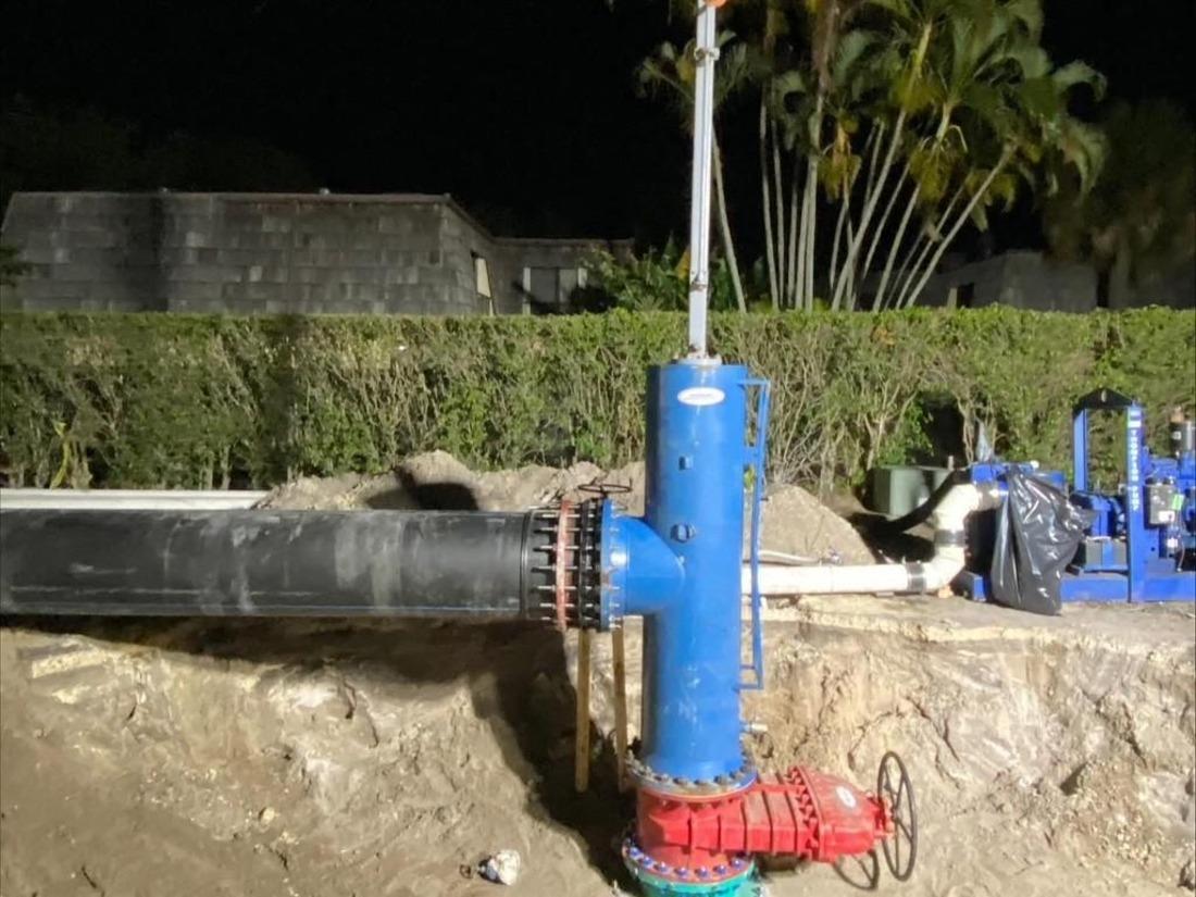
Single- and double-line stop configurations shouldn’t serve as shorthand for “unsafe” and “safe.” Either one depends on a suitable fitting and a head that seals against the real pipe condition. Crews also need a way to verify pressure status on the side where work will occur.
The consequences of seepage change with the task. Minor leakage may be manageable during work that never opens the pipe, but it can prevent a cut-out section from reaching a confirmed zero-energy state. Where crews will break containment, the plan needs controlled drainage and continued pressure monitoring rather than assuming a seated head is holding perfectly.
Contingency planning belongs in the original configuration decision. If one head doesn’t achieve the expected seal, the team should already know whether it can reset the equipment or install another isolation point. That response becomes much harder to develop after the pipe has been opened.
The most important thing to remember is that line stops are temporary, so the plan must account for their removal before installation starts. After the work is complete, operators generally restore pressure in a controlled manner and equalize across each head before retrieval. Rushing that transition can create avoidable movement in the system or place unnecessary load on the equipment.
Once the stopping head is removed, a completion plug seals the access fitting so the temporary valve can come off. The fitting then receives its final closure and may remain available for future intervention if its design permits reuse. Placement decisions made for today’s job can therefore affect access during the next repair.